 A cell was set up with a large Graphite Anode and Copper Cathodes to investigate current and Voltage waveforms. The Anode current density was approx. 40 to 48mA per square cm. The cell was cold at approx. 14°C.
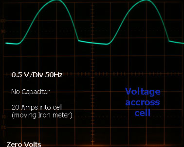
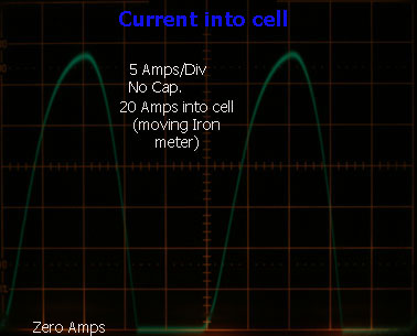
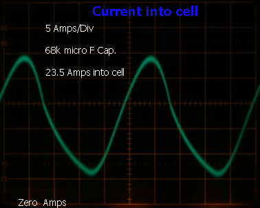
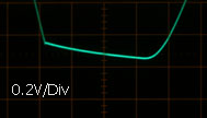 The traces above show the current and Voltage waveforms at the Chlorate cell when supplied with raw DC from a rectifier (no smoothing capacitor). The Voltage waveform accross the cell looks a bit strange. There is a slopeing part between Voltage pulses (when current is at Zero). The current appears to stop going into the cell when the Voltage goes down to 2.85 Volts. Perhaps this indicates the (often mentioned in the scientific literature and measured with a third, 'reference', electrode) minimum Voltage required to make Chlorate. The slope that can be seen would appear to be an exponential Voltage drop down to 1.3 Volts where battery action keeps the Voltage accross the cell at 1.3 Volts (Graphite Anode, Copper Cathode). The exponential nature of the slope is noticed when the supply is disconnected from the cell and the scope line is seen to drop down to 1.3 Volts over a period of approx. three seconds in an exponential fashion. A magnified view of the slope is shown at left. It is of no major practical significance to the home Chlorate producer.
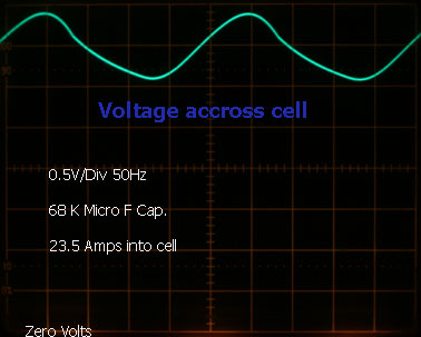
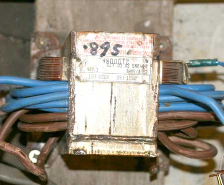
A large transformer with a core area of 49 cm squared with 24 turns on the core (inductor of 0.73mH as measure with a multimeter with no DC current going through the inductor) was available and used in order to see how much it would help to give a smoother current into the cell along with the capacitor. The current ripple decreased by approx. half but the total current into the cell (on moving Iron meter) decreased down to approx. 9 Amps. The Variac was used to bring back the cell current to 23.5 Amps. Since most home Chlorate makers will not have access to a transformer core of this size and since it does not have a very dramatic or useful effect on the current drawn by the cell, the addition of an inductor was not investigated any further.
Using an MOT with some turns of heavy wire, had no visable effect on the current drawn by the cell. It was pointless trying to obtain a smoother current as the inductance available from an MOT core (air gapped or not) was far too small.
The circuit below shows the setup for this discussion.
HIT THE BACK BUTTON ON YOUR BROWSER